Sheet Metal Tolerances Explained: Achieving Precision in Fabrication
When fabricating sheet metal, achieving precise tolerances is critical for producing high-quality parts that meet functionality requirements without unnecessary costs. However, understanding the correct tolerance settings for different processes and materials can be challenging.
In this post, we’ll explore the different types of sheet metal tolerances, common issues engineers face, and best practices to get the most out of your fabrication process and product design.
What Are Sheet Metal Tolerances?
Sheet metal tolerances define the permissible variations in a part’s dimension so it fits, functions, and performs correctly in its intended application. These tolerances affect everything from the edges of parts to hole placements, and their application depends on the manufacturing method used. They are often specified for various features, such as type of metal, holes, edges, bends, and overall part dimensions.
There are two main categories of tolerances:
Standard Tolerances: The default tolerances, often based on industry standards, define the allowable deviations for sheet metal parts. Due to the nature of the material and the forming processes, these tolerances are typically looser than those for machined parts.
Critical Tolerances: These are more stringent and are often applied to critical features for part functionality, such as bolt holes or mounting points.
Common Issues with Default Tolerances
One of the main issues in the design process is when engineers use default tolerance settings in computer-aided design (CAD) programs like SolidWorks. As Scott, Engineering Manager at Herold Precision Metals, points out, SolidWorks is designed for machining, where tolerances are much tighter than what is generally needed for sheet metal parts. This often leads to over-engineering and higher costs.
“Machining tolerances are much tighter than sheet metal tolerances,” explains Scott. “A typical tolerance for sheet metal might be plus or minus ten-thousandths of an inch across a bend, while machining tolerances could be much finer.”
In sheet metal fabrication, the goal should be to balance precision with cost-effectiveness. Using tighter tolerances than necessary can cause delays and increase costs, especially when certain features could be manufactured with looser tolerances without sacrificing functionality.
How Tolerances Affect Fabrication & Cost
Tolerances significantly influence both the complexity and cost of the fabrication process. Tighter tolerances can complicate production by requiring additional steps, such as post-forming machining. For instance, if a hole needs to be positioned with tight tolerances relative to a formed edge, it may require machining after the part is formed, adding time and cost.
Tighter tolerances can also impact quality control and inspection processes. “Machining tolerances on sheet metal parts can slow down the process and increase costs because they require more complex, time-consuming methods and reduce production part yield,” says Bob, VP of Sales & Marketing at HPM.
Setting the right tolerances for each feature is important to keep fabrication cost-effective. While critical holes and functional features may require tighter tolerances, less critical areas can often tolerate looser settings. Being realistic about tolerance requirements reduces costs and helps companies offer more competitive pricing and quicker turnaround times.
Best Practices for Setting Sheet Metal Tolerances
When setting tolerances for sheet metal parts, it’s important to be thoughtful and mindful of the manufacturing process. Scott recommends the following best practices:
Collaborate with Engineers Early: The earlier engineers, quality control teams, and fabricators collaborate, the better. Understanding the limitations of the manufacturing process upfront can prevent unnecessary delays.
Match the Tolerance to the Function: Not every feature on a sheet metal part needs to be manufactured to tight tolerances. Focus on critical features that affect functionality and consider looser tolerances for non-essential areas.
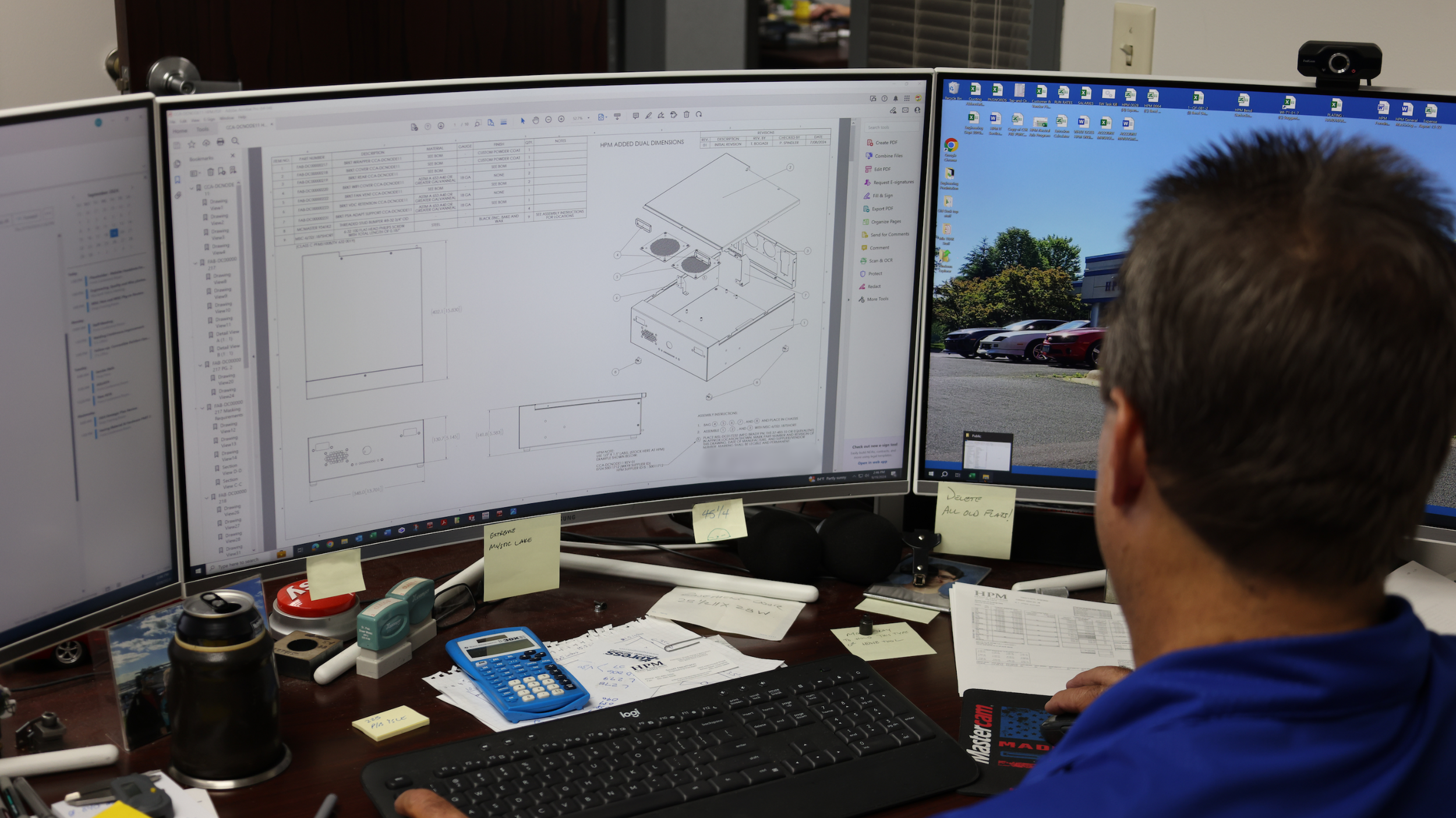
Use the Model to Drive the Print: The CAD model needs to be up-to-date and reflect any changes in the part design. The print should be a byproduct of the model, not vice versa.
"Models and prints should always match. If you need to make adjustments, change the model first and generate a new print," Scott advises.
Final Thoughts: Achieving Precision with the Right Tolerances
Achieving the correct sheet metal tolerances is crucial for balancing precision, cost, and performance. By working closely with engineers, being mindful of the manufacturing process, and setting realistic expectations, you can avoid common issues and get high-quality results.
Do you need help with your sheet metal fabrication projects? At Herold Precision Metals, we work closely with engineers and manufacturers to provide precise results. Contact us today to learn how we can assist with your sheet metal needs.


